When I first came across Alfred Security software making use of old phones for video surveillance, I immediately got an idea for such a project. Namely, old phones have weakened batteries too. They drain out fast and need frequent recharging. If you connect them to the charger forever, you get a problem of overcharging, overheating, and even danger of fire.
The Smart Charger comes to the rescue.
It uses the phone's battery sensors to control when to charge and when to live off its battery. The hardware and the phone communicate through a Bluetooth connection, readily available on all phone models.
Hardware is simple and affordable. All this project needs is:
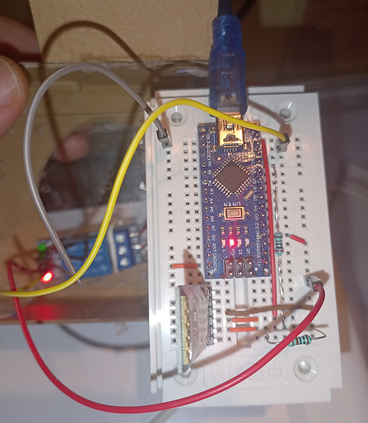
Connections will probably look much clearer on schematic drawing.
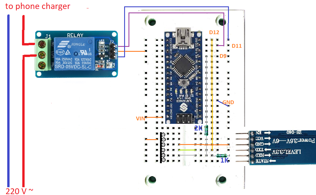
All software code shown here is for this particular wiring. It is off course possible to use different Arduino pins for a job, but software will have to be updated accordingly.
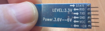
The HC-05 is an inexpensive module that is compatible with wide range of devices including smartphone, laptops and tablets. It is not Low Energy module, but full Bluetooth module.
After filling the breadboard accordingly, the first step should be connecting Arduino Nano with the PC to set up the Bluetooth module.
You can set up various setting in the HC-05 module like the device name, pass-code, modes of operations, configuring one as Master and other as Slave and all of that with the help of AT commands.
You don't have to configure the module, you may use it as it comes, but then it will be discoverable under generic name "HC-05" and Pin code for pairing would be default "1234".
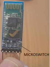
Notice the tiny microswitch on the board on the top end of the switch, it is used to put the board in the AT command mode.
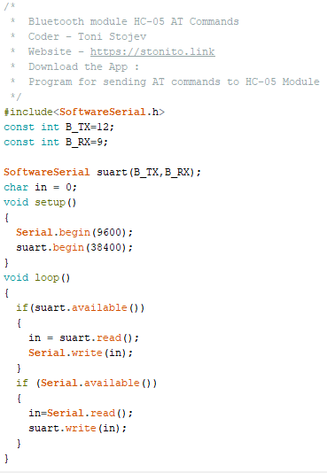
Both NL & CR. Send AT, it should return OK. This is checks all is okUse following commands to set name and pin code of the module.
| Command | Response | Description |
|---|---|---|
| AT+NAME="Smart Charger" | OK | Sets the name to Smart Charger. |
| AT+PSWD="1111" | OK | Sets the password for PAIRING. |
All AT commands HC-05 supports are listed in following document.
All pins and their function are explained in the table below.
| Pin | Description |
|---|---|
| State | Can be connected to the Arduino Digital Input to monitor the state of the connection, Paired or Disconnected. |
| Rx | Receive Pin of the module. It is recommended to use a voltage divider as shown in the wiring.
The reason is that TX and RX pins on module side works on 3.3V, as indicated.
Arduino Digital outputs are, as you know, 5V. To be safe, you can use divider to adjust the limit.
Why 2K and 1K resistors? 5V * 2K / (2K+1K) = 3.3333 V .
|
| Tx | Can be connected directly to the Arduino Rx Pin. 3.3V voltage level is high enough to be recognized as HIGH on Arduino side. |
| GND | Connected to GND pin of Arduino |
| 5v | VCC, power to the module |
| EN | Enables or Disables the module. |
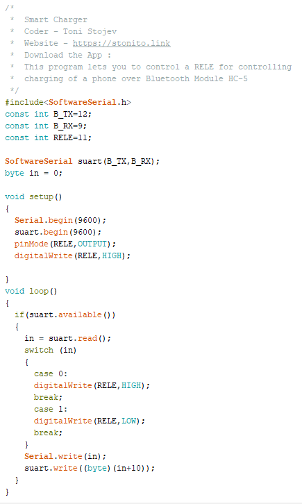
Code is quite simple. Receives commands as single bytes 0 or 1, for switching Relay On and Off. It returns to the Bluetooth sender the same byte increased by decimal 10, to be used on Bluetooth sender side as a confirmation of a command received and executed orderly.
Software is written in Visual Studio 2022 Community Edition, using Xamarin Forms.
Although it is simple in appearance, it was not easy to write. That's why I don't provide source code, just a basic explanation and APK for download, for those who want to use it.
Application expects running hardware, as explained above. The hardware must be in working range of Bluetooth connection with the phone. Phone must be paired with the module, and module must have the name set to "Smart Charger".
Phone establishes connection to Bluetooth module by looking at paired (bonded) devices, look for the first one named "Smart Charger", and connects to it. So, you may use more Smart Chargers in close range, but they will not interfere with each other if the phone is paired with a single and correct Smart Charger.
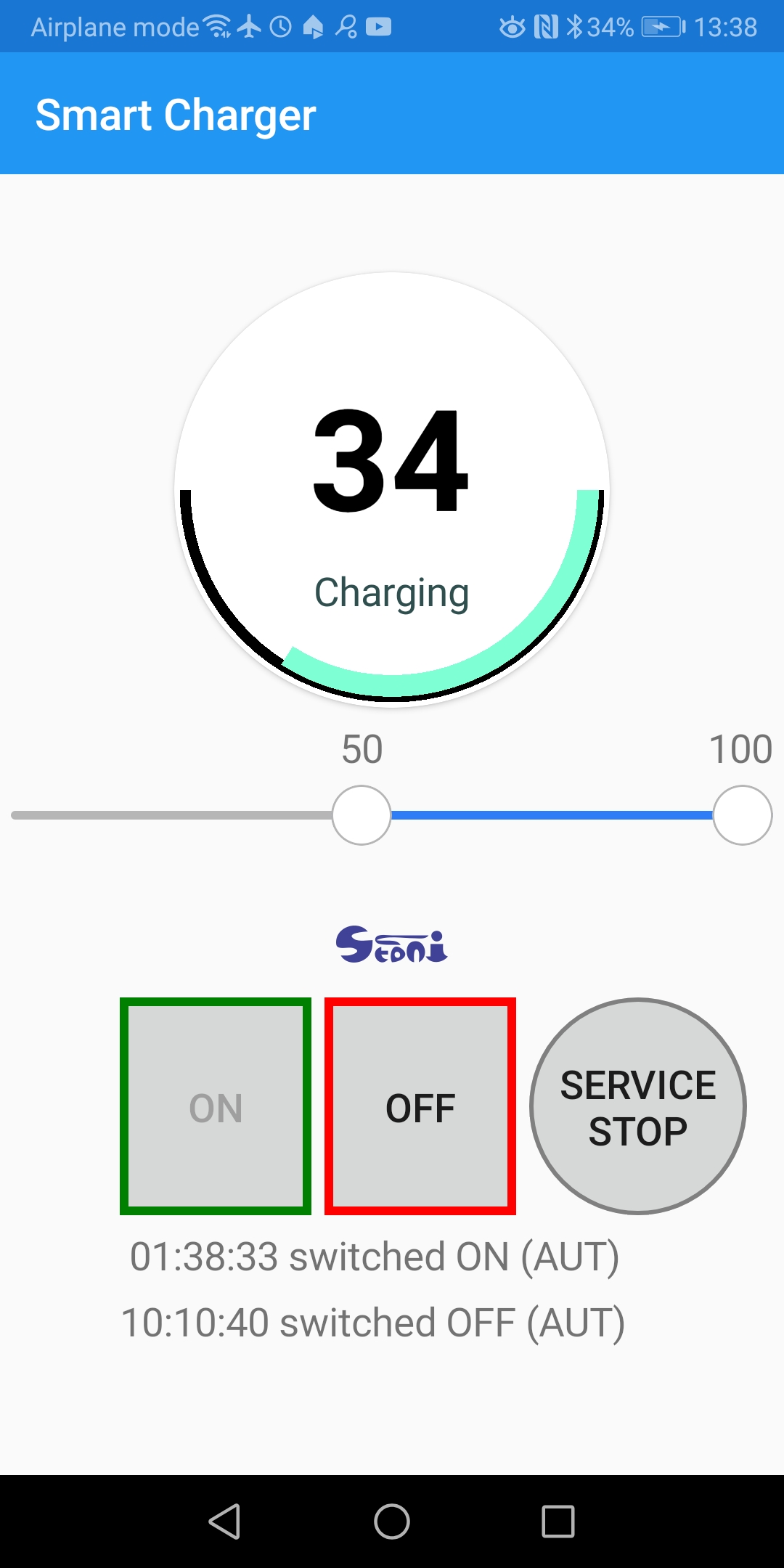
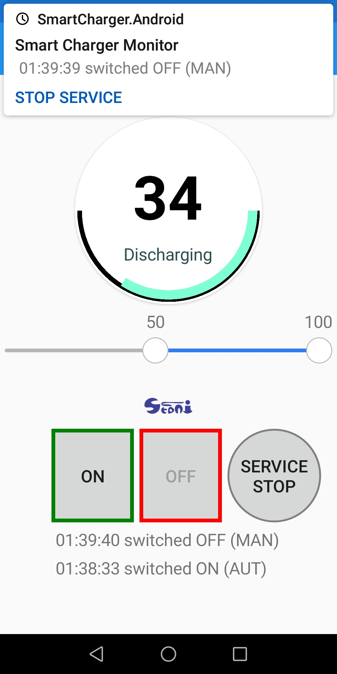
The round gauge control containing battery status information dominates the main form.
The gauge starts from 3 o'clock and continues clockwise. The positions of the two handles of the range slider below are also in the gauge control.
Those are limits upon which the automatic switching charger on or off should occur.
The lower value means that the charger will always be ON when the battery level is in the black zone.
The upper value means that the charger will always be OFF when the battery level is in the red zone. The thick red line is not visible when the upper limit is 100%.
Green is the actual battery level of the phone.
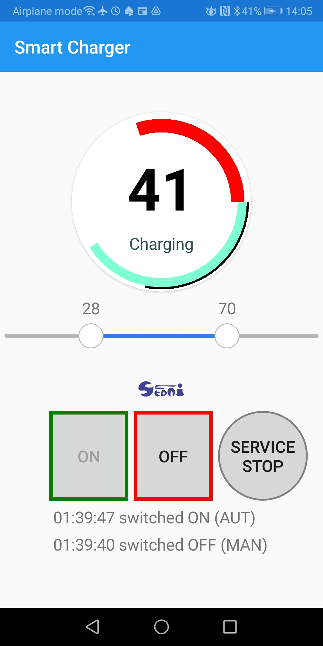
Limits are now 28 and 70 percent. You see the red line stretching from 70% and going to 100% (3 o'clock on the circle).
The battery charge level is now in the middle zone, so an automatic process will not change the charge status. In this state, you can switch the charger manually as you want. It will keep that state.
Moving those two handles in a range slider is all you have to do to configure the charging process.
All other is happening automatically.
Commands to switch the charger on or off are going via Bluetooth connection.
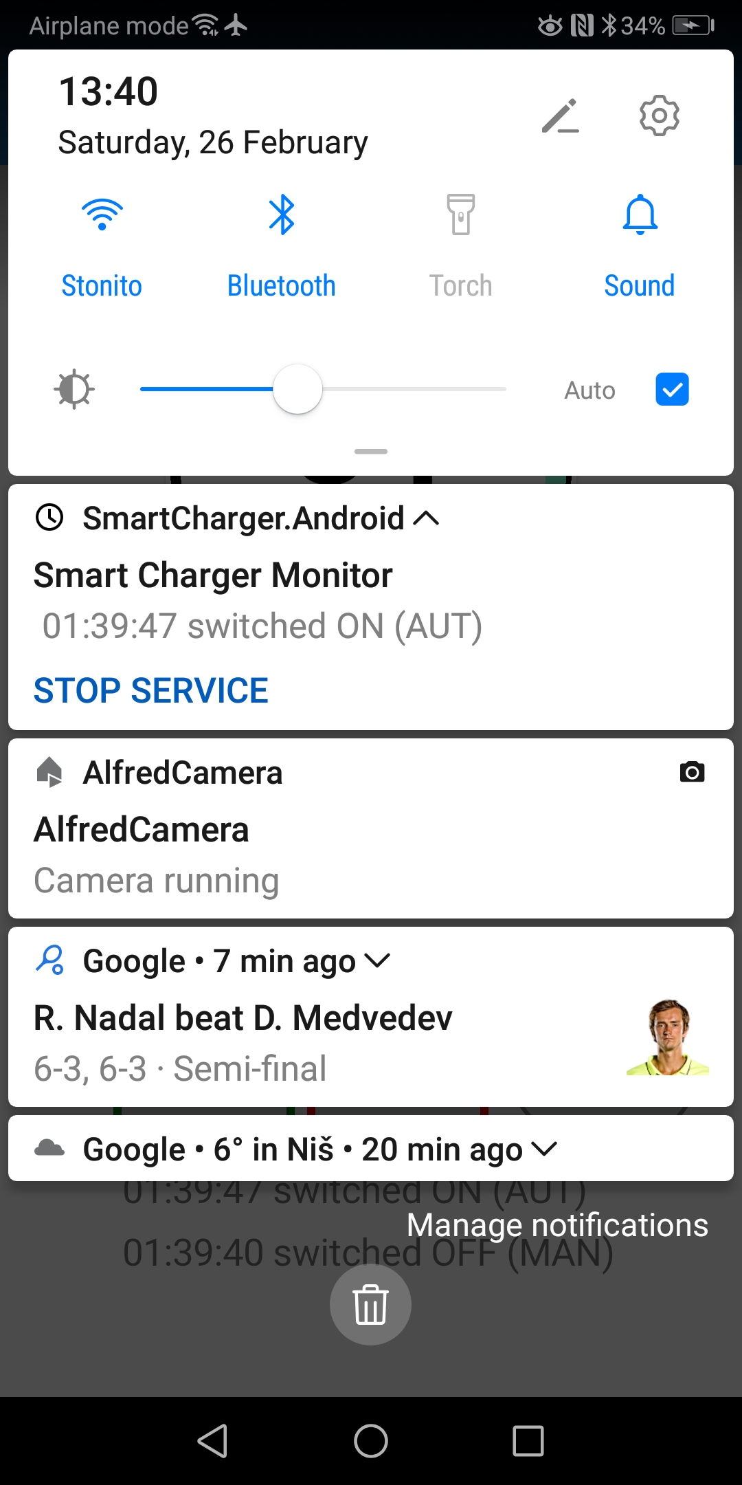
The Foreground Service performs both the Bluetooth connection and automatic switching process.
For those who don't know what is a Foreground Service, it is a special type of service in Android, that can survive for a longer time.
Android system is notorious for silently killing background services when it senses a lack of memory or other resources.
But foreground service has to maintain notification in the notification area of your phone, as long as it is active.
Manual switching (ON/OFF) buttons send a message to the service about your intention.
Service periodically checks (every 5 seconds) for pending actions.
First, if checks are there any manual switching requests. It remembers only one request in the last 5 second periods.
It means if you press ON, and then OFF again, only OFF will be executed, if both clicks happened inside one 5 seconds interval.
If there is a command, it has a priority, it executes, and then the service sleeps again for another 5 seconds.
If there is no command, the checks are performed on the current battery charge level and limits for switching charging.
If action is needed it is executed and notification is issued.
If log-entry contains time and action performed it means everything was as expected. Communication over Bluetooth initiated, the command sent, the command received, the command executed, and return-code received and checked for validity.
If not, the error log will contain the error encountered.